

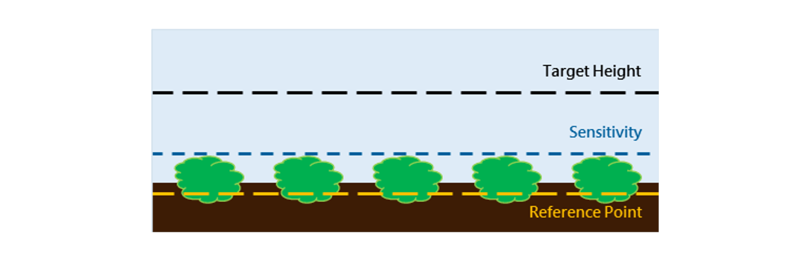
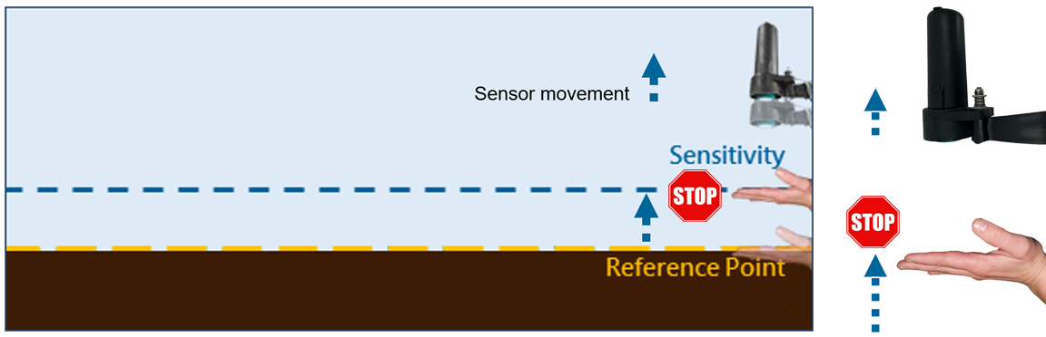
 This scenario works best for emerging or sparse canopy conditions because the ground is a more consistent reference point.
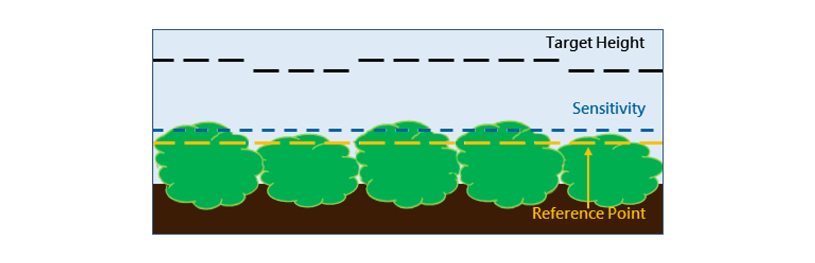 This scenario works best for mature and full canopy conditions. Ideally you will need to adjust your Sensitivity throughout the season as the crop matures.
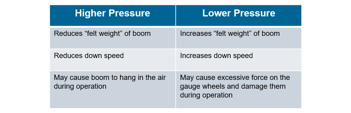
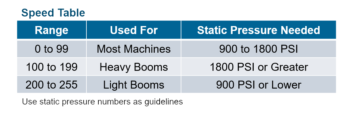 The speed ranges are based on the static pressure it takes to keep the booms level. The heavier the booms the more effort it will take to raise them.
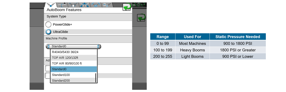


AutoBoom UltraGlide Calibration and Fine Tuning
This video will guide you through an AutoBoom UltraGlide system calibration. It will also show you what you should do after a calibration to ensure the system is finely tuned.
View ResourceLearn more about Raven's legacy AutoBoom height control system. We will cover its components and what they do, discuss best practices, describe how the system works, go over how to fine-tune the system, and learn some basic troubleshooting areas.
Need help? Contact us for assistance.
Have feedback? Let us know!
 |
A Raven Legacy Learning Series |
| Would you like to learn more about Raven's legacy AutoBoom height control system? Then, you have come to the right place! We will cover the different control types, their components and what they do, describe how the system works, discuss best practices, explain how to fine-tune the system, and finally you will learn some basic troubleshooting steps. If this is your first time through the course, please start at the beginning and continue to the end of the series. You can then jump to a section for further review on subsequent visits. |
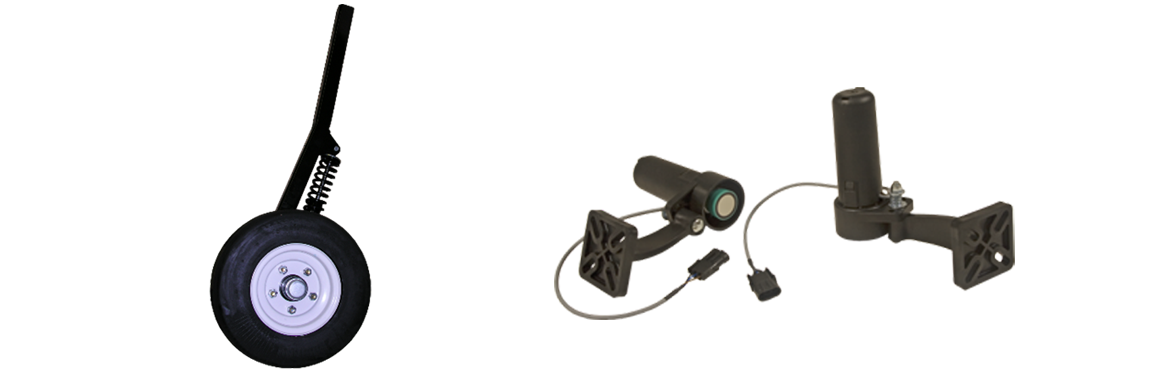
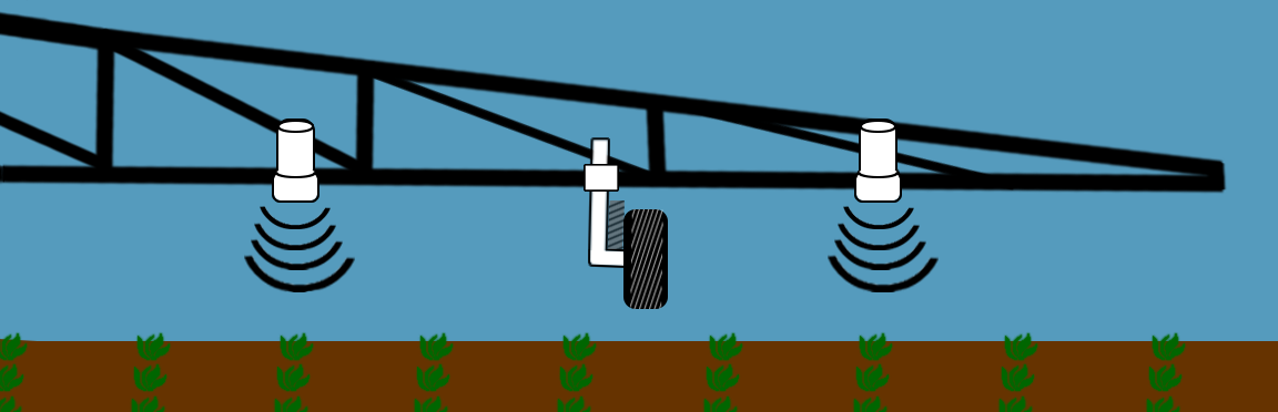
The AutoBoom system maintains optimal spray height with either cushioned gauge wheels or ultrasonic sensors. The system uses the ground or crop canopy information and adjusts the booms to stay within its intended height position. As a result, the boom stays closer to the target height with less variability, maximizing boom life and minimizing crop damage. |
AutoBoom comes in two options: and UltraGlide which uses ultrasonic sensors to "see" either the ground or the crop canopy. You can also operate the AutoBoom system with a combination of both control options; whereby either the cushioned gauge wheels or the ultrasonic sensors are the primary control component. Must order either the gauge wheels or ultrasonic sensors and cabling separately. All three variations can be used on both pull-behind or self-propelled sprayers. |
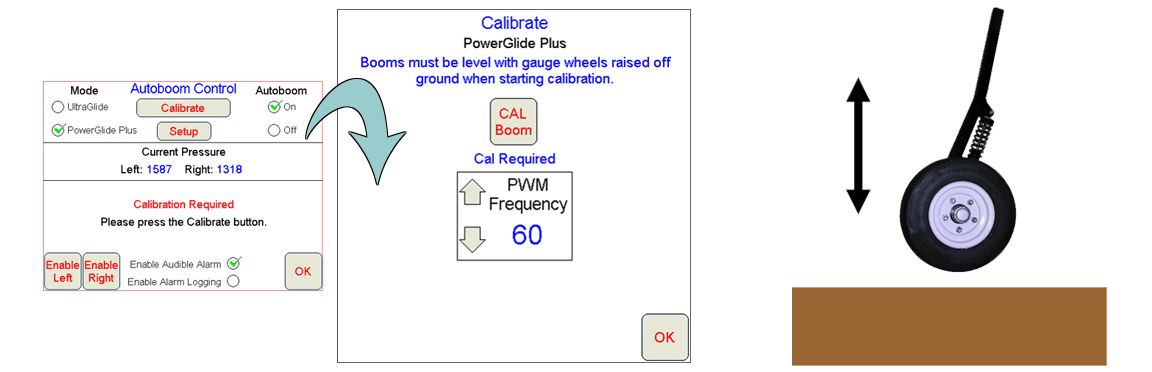
PowerGlide Plus is a pressure-based system. Adjust the length of the wheel axle for height tolerance, typically up to 6 inches above the ground. Set the pressure for how sensitive you want the gauge wheels to be if they touch the ground to maintain the spray height while operating in the field. |
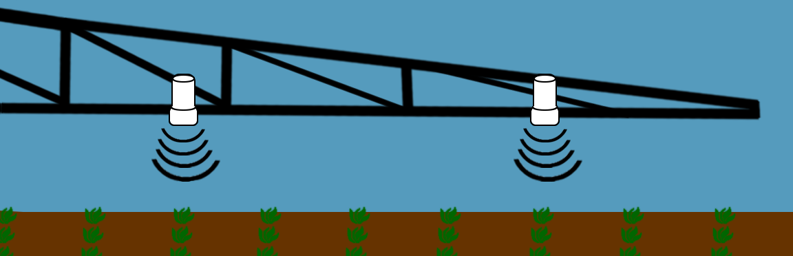
With UltraGlide, you just set the boom height you want to maintain while operating in the field. The height setting can be from the ground or top of the crop canopy; but you must choose one or the other as the reference point. |
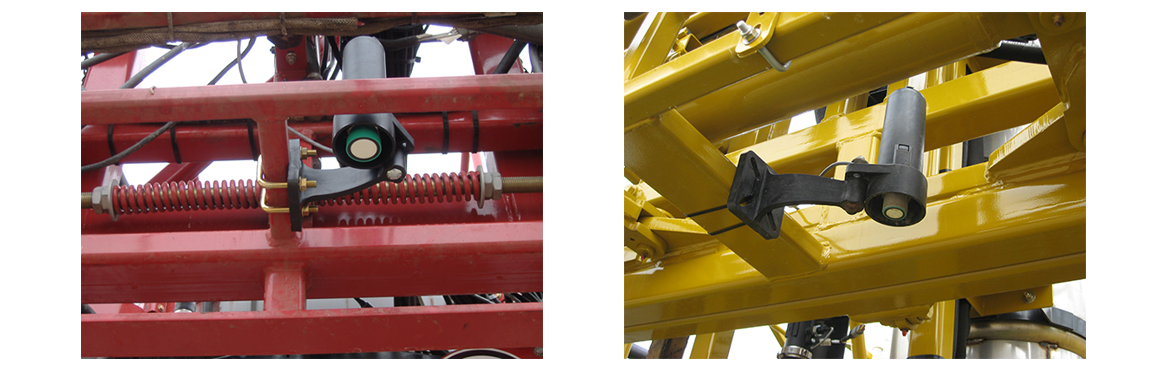
A typical UltraGlide installation for narrower booms like 100 foot and smaller would typically include three sensors. One sensor on each side and one sensor on the center rack. |
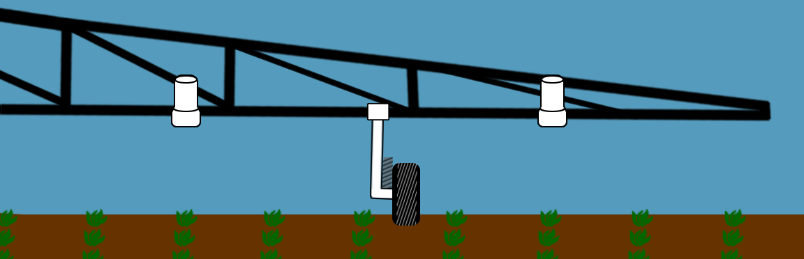
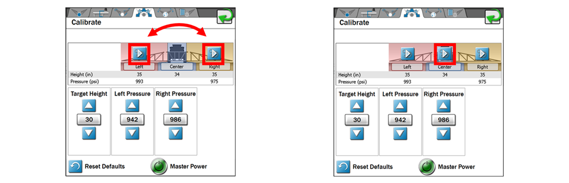
UltraGlide in PowerGlide Plus Mode |
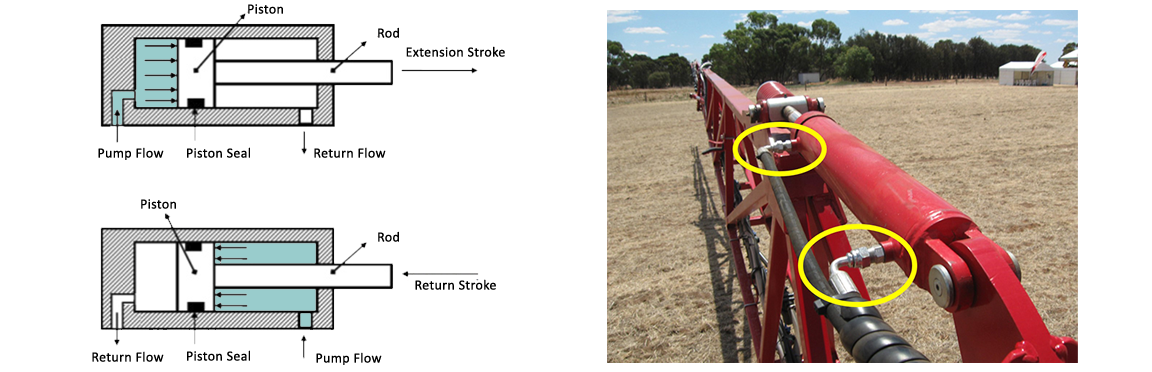
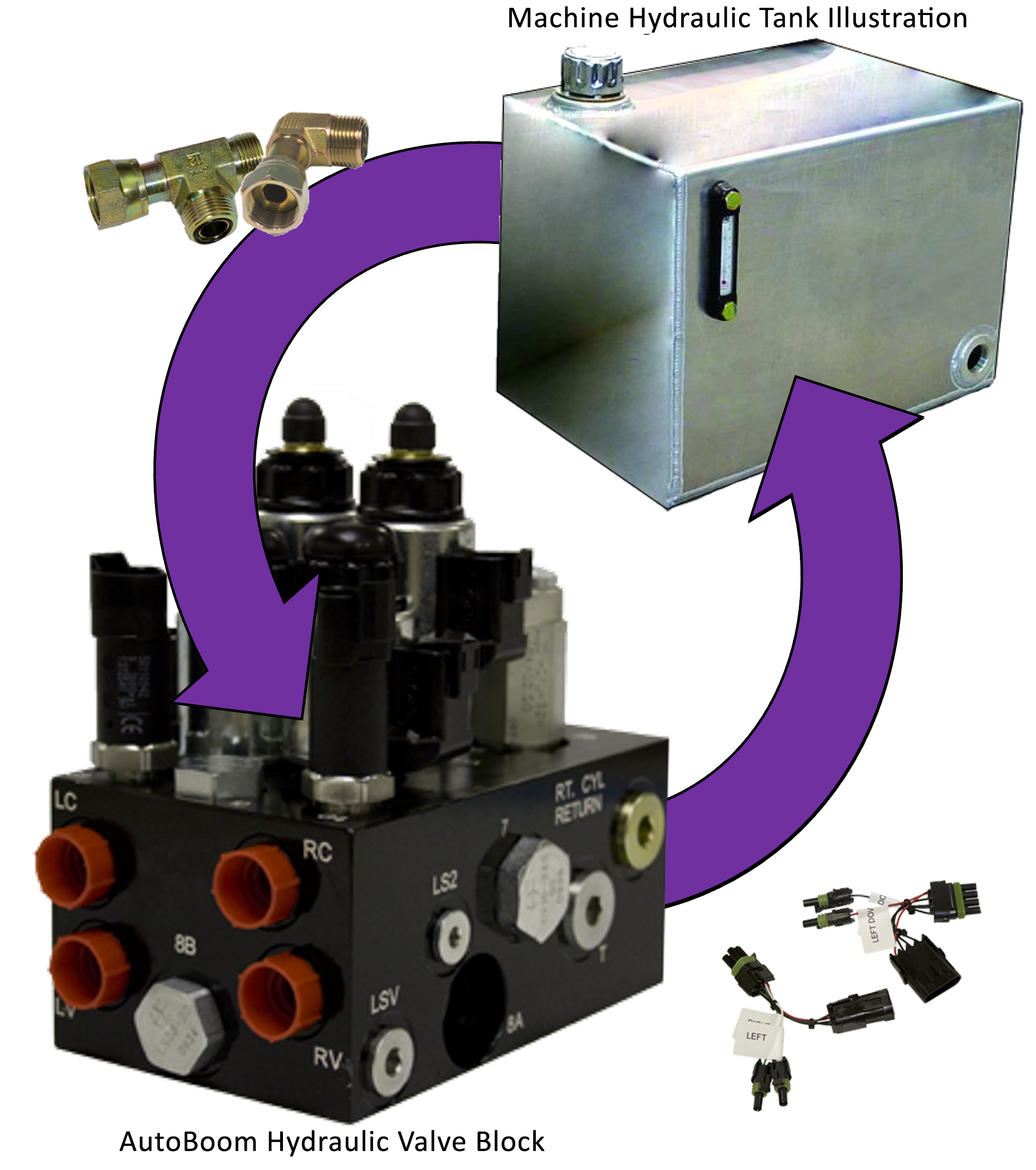
AutoBoom is not intended to be a closed hydraulic system. With pull-behind sprayers, it is recommended to install the Autoboom system as open center to prevent high operating pressures and excessive hydraulic heat buildup. |
|
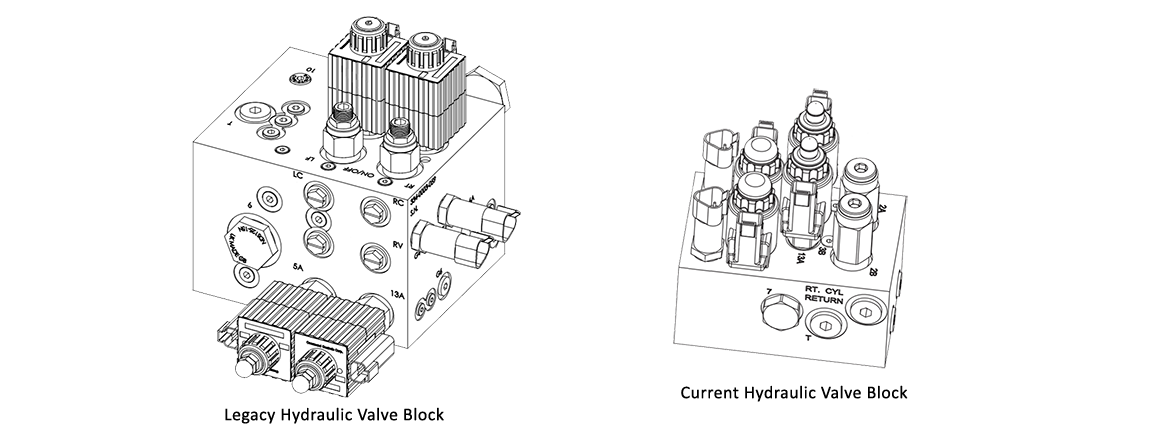
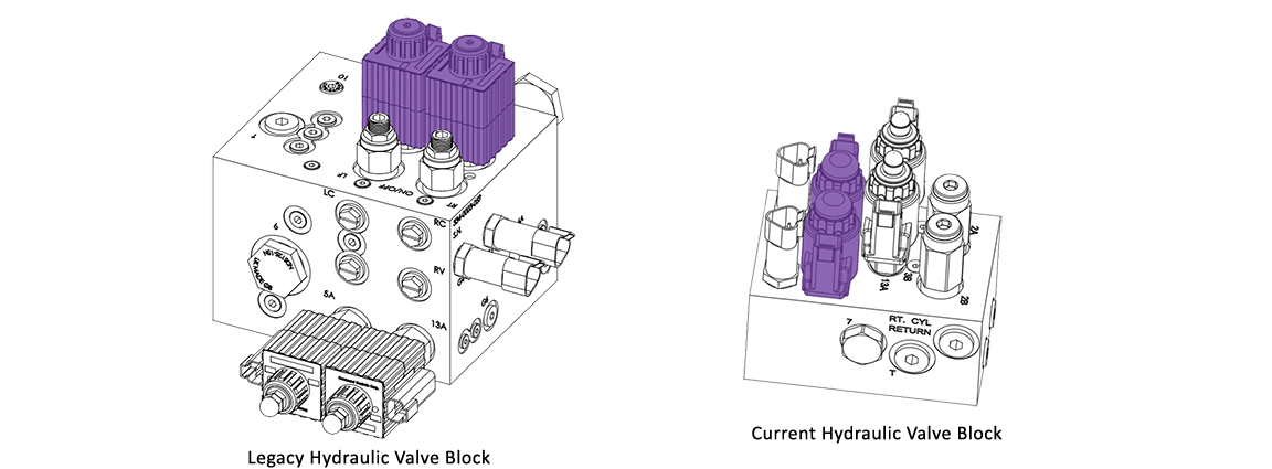
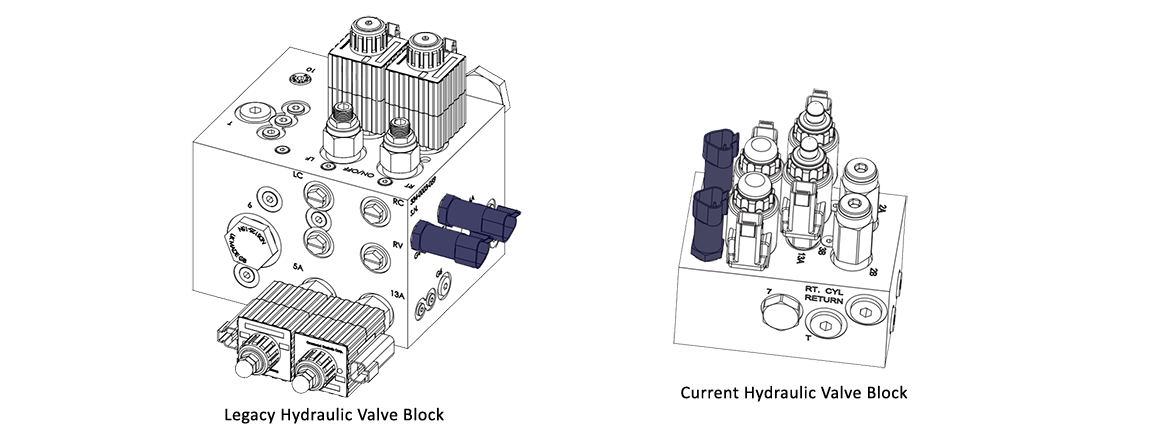
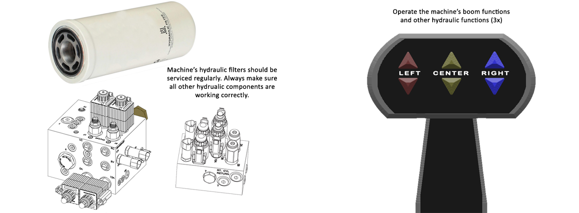
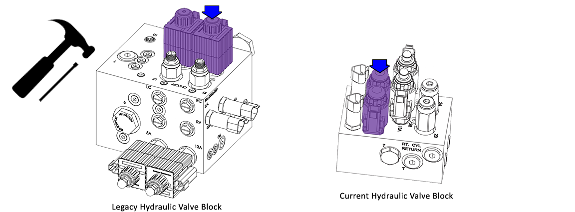
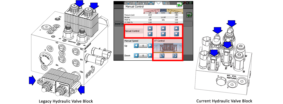
Both the PowerGlide Plus and UltraGlide systems will have their own hydraulic valve block. The left valve block is from the legacy systems and the right valve block is the current version for both systems. Even though the current version is smaller, it has the same hydraulic capacity of the larger legacy valve block. With some factory-fit machines, the AutoBoom valve block has been modified to mount directly to the machine valve block as with some Agco Rogator sprayer models. With other machines, like Equipment Technologies Apache sprayers, the AutoBoom valve block components have been integrated into the machine valve block.
|
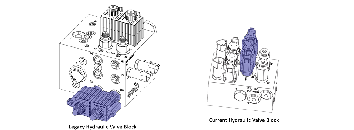
Design Changes |
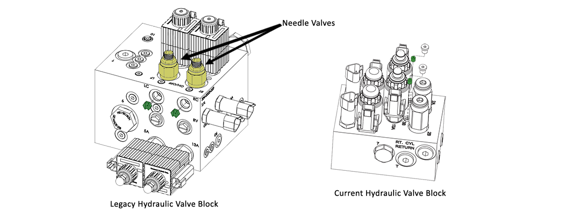
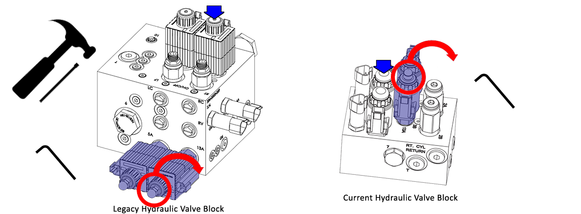
Blocker Cartridge Valves |
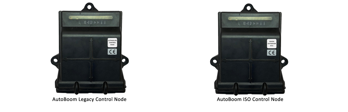
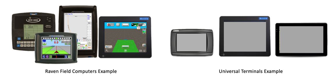
The AutoBoom system comes in two versions, either Raven proprietary CAN bus or universal ISO CAN bus (International Organization for Standardization) which makes it an ideal height control system for most sprayers. |
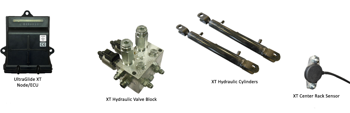
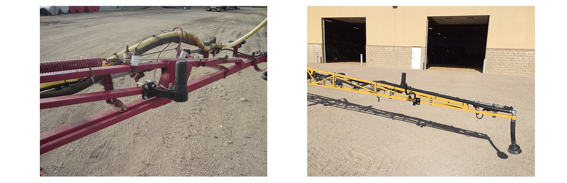
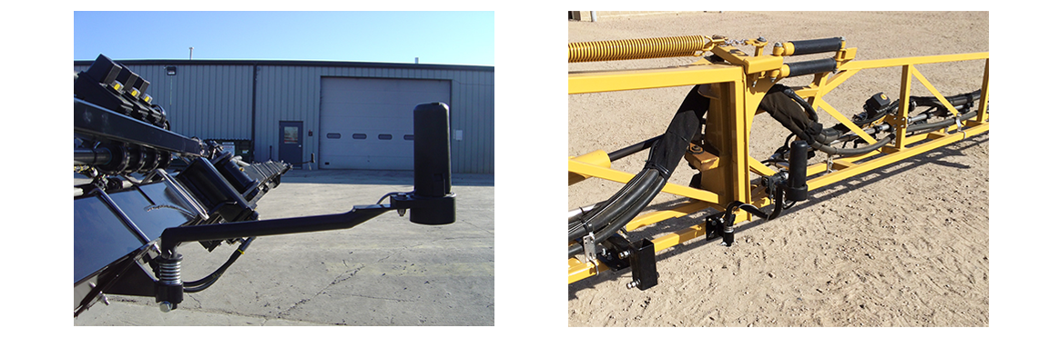
For extreme field conditions, an additional hydraulic system can be installed with the UltraGlide system. The UltraGlide XT system includes its own Raven proprietary node or ISO ECU, its own hydraulic valve block that is coupled with the AutoBoom valve block, separate hydraulic cylinders that replace the springs or dampeners on the machine center rack, and a center rack sensor. The gyros in the XT node or ECU measure machine roll and compares that reading to the center rack position provided by the XT Center Rack Sensor to help stabilize any excessive center rack movement. The UltraGlide XT system is a great addition to the UltraGlide system on many pull-behind sprayers or self-propelled sprayers that have excessive movement in their center racks.
|
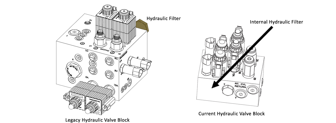
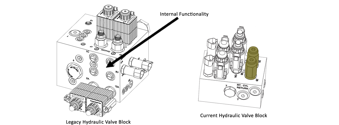
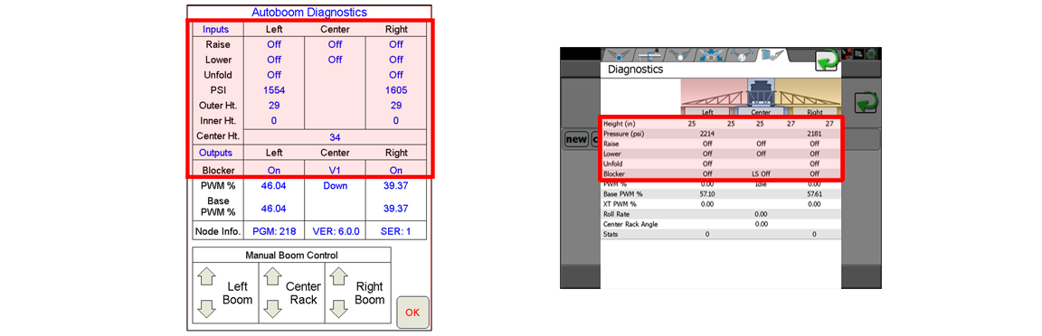
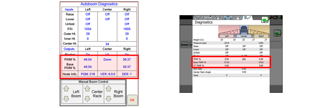
In most cases, you will no longer be installing an AutoBoom system for the first time. It is still recommended that the hydraulic filter(s) be changed on a regular basis and that all other hydraulic components are working correctly as well. Remember that the current AutoBoom valve block has an internal filter that is not serviceable. The legacy AutoBoom valve block filter should be serviced regularly as well. It is always a good idea to operate the machine’s boom functions manually to make sure everything is working correctly before operating the AutoBoom system for the first time or at the start of a new season or when troubleshooting the system. |
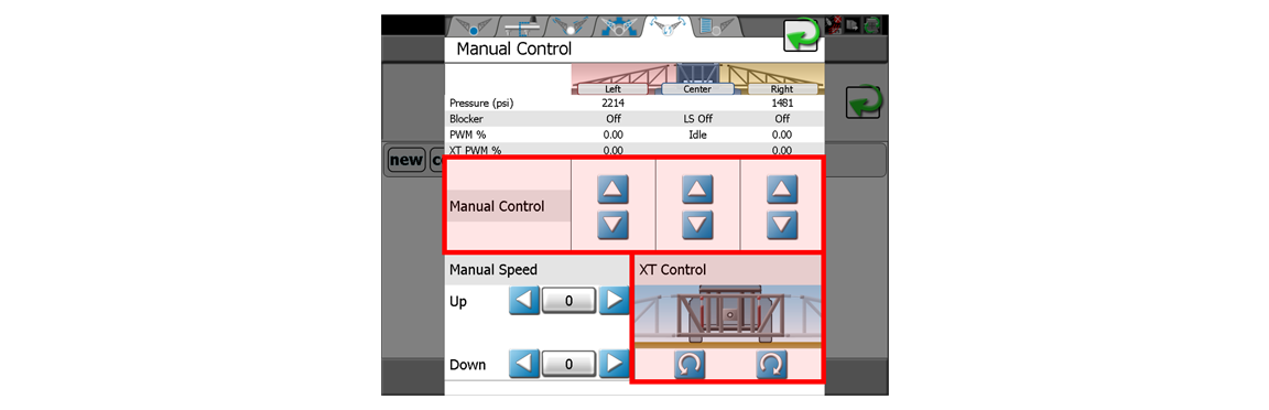
Once the machine boom functions have been validated with the machine's boom switches, it is good practice to manually control the boom functions from within the AutoBoom control pages or through the AutoBoom Object Pool if using the ISO system. This routine check should be completed after a new install, at the beginning of each season, or any time the system is not operating correctly. If UltraGlide XT is installed, it will have its own manual control section. [screenshot from Viper 4/Viper 4+] |
UltraGlide |
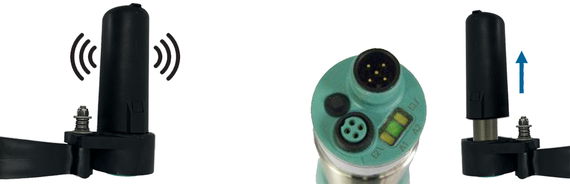
Sensor Placement Sensor Properties |
PowerGlide Plus UltraGlide |
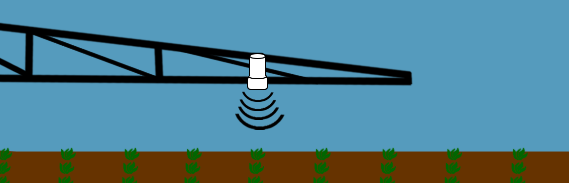
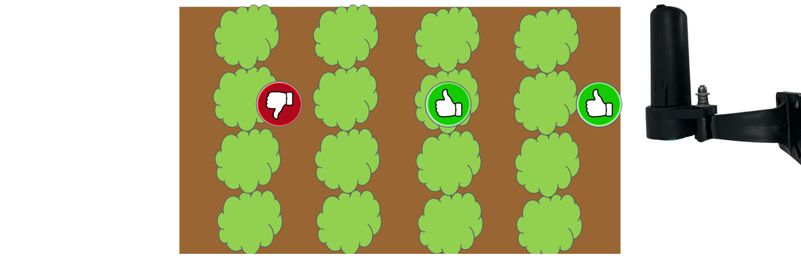
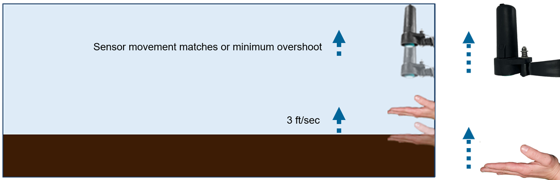
Sensitivity determines how reactive the UltraGlide system will be when there are changes in height from your Reference Point. Do you want the system to raise and lower the boom with small changes in the height reading or do you want it to ignore some height differences? In the illustration below, the Reference Point is the ground. |
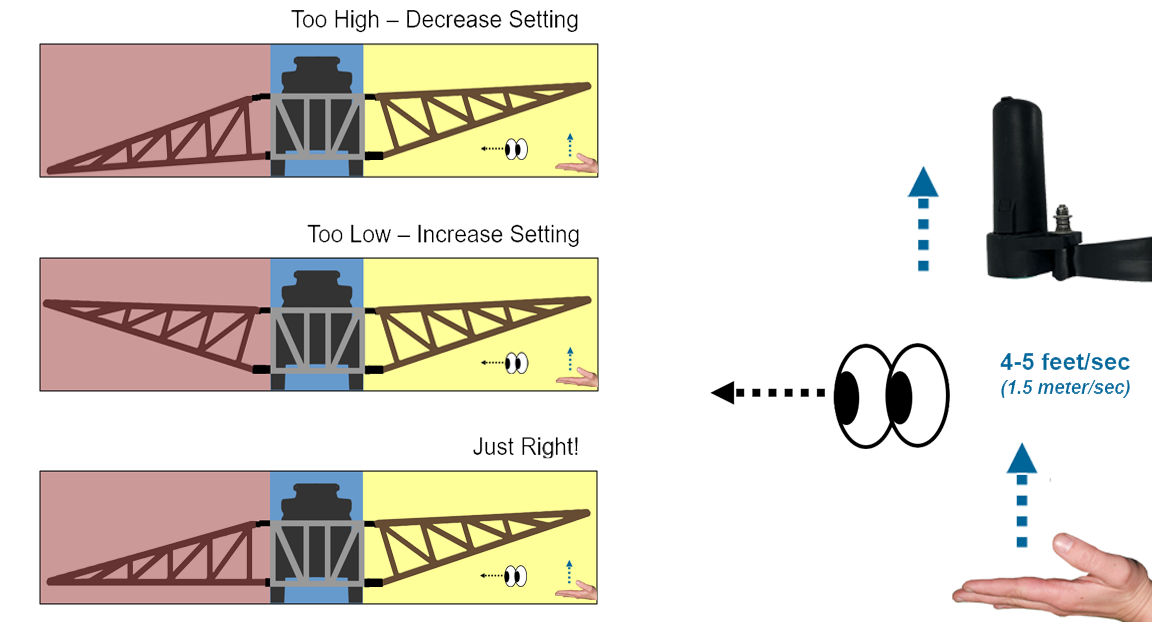
Once Sensitivity is set, you can adjust how fast the UltraGlide system will raise the booms to any detected height changes. The Speed Setting is only for raising the booms. The time it takes to lower them is not configurable and is pre-determined by the speed range. During setup, you can select your sprayer from the machine database. This selection will place you in one of the three speed ranges shown below. |
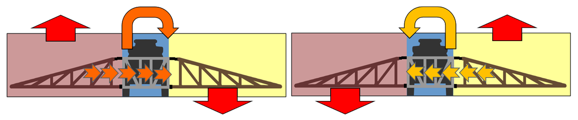
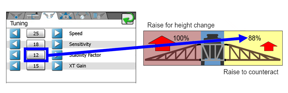
| Boom Physics We will want to counteract the effect of raising one boom at the Speed setting with respect to the opposite side movement. Depending on how rigid or loose the machine center rack is, the force of raising one side may transfer the energy to the opposite side and cause it to drop.
|
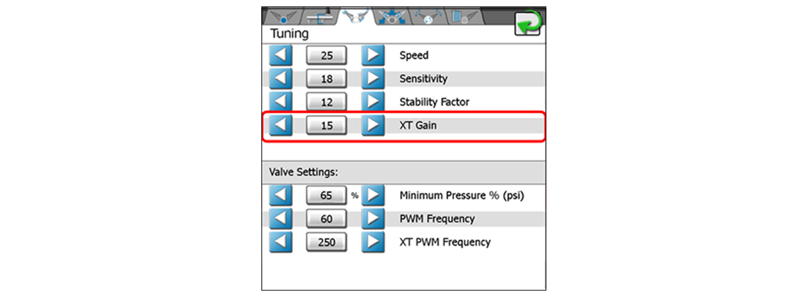
| XT Gain With extreme field conditions, Stability Factor might not be enough to counteract the boom movements. This is where UltraGlide XT would be a good solution. The XT Gain setting can be adjusted accordingly to make the center rack operate more rigid or loose. Raise the value if you would like the center rack position to be maintained more aggressively in relation to the machine chassis roll; or lower the value to lessen the effort to maintain the center rack position. |
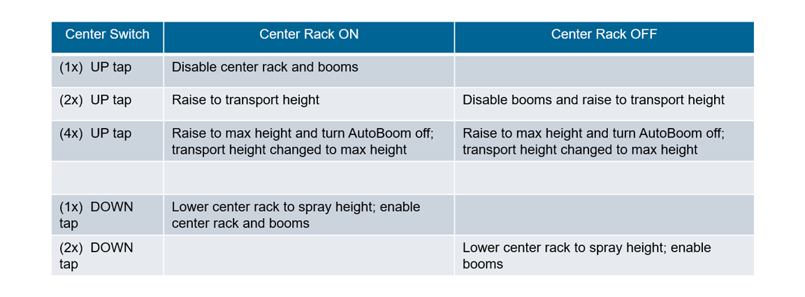
| Center Rack Switch There are some pre-programmed functions for certain up and down button presses. For the Center Rack switch, the button sequence depends on if Center Rack Control has been enabled. The table below shows the tap sequences: |