
SmarTrax Steering Overview
This video covers the different SmarTrax options as well as how to fine tune a system. Also learn what to consider for installation, GPS settings, and what to look for if you need to troubleshoot.
View ResourceLearn more about Raven's legacy SmarTrax 3D auto-steering system. We will cover its components and what they do, discuss best practices, describe how the system works, go over how to fine tune the system, and learn some basic troubleshooting areas.
Need help? Contact us for assistance.
Have feedback? Let us know!
 |
A Raven Legacy Learning Series |
| Would you like to learn more about Raven's legacy SmarTrax 3D auto-steering system? Then you have come to the right place! We will cover its components and what they do, discuss best practices, describe how the system works, go over how to fine tune the system, and learn some basic troubleshooting areas. If this is your first time through the content, please start at the beginning and continue to the end in series. You can then jump to a section for further review on subsequent visits. |
|
SmarTrax 3D is a legacy Raven auto-steering system that operates on Raven's proprietary CANBUS communication protocol. It takes a GNSS correction source, compensates it for changes in terrain, and then steers the machine to a set guidance path. The control method for SmarTrax 3D can either be hydraulic through the use of a hydraulic steering valve or mechanical through a mechanical drive unit installed on the machine's steering column. And importantly, SmarTrax 3D can only be as accurate as the GNSS source, and it cannot perform better than the capabilities of the machine. We will go into more detail of these points throughout this resource. |
|
A Raven proprietary CAN system uses Raven-specific communication protocols. This system configuration only works with Raven CAN devices and does not support other manufacturers' devices unless specifically coded to work on the CANBUS. Raven CAN devices include field computers like the Cruizer II, Envizio Pro, Viper Pro, and Viper 4, and CAN ECUs like AutoBoom, SmarTrax 3D, and Sidekick Pro. |
|
the user interface The field computer is how the user interacts with the other devices in the system. For SmarTrax 3D, you will perform all configuration, calibration, and fine tuning through the field computer. One thing to note is that unlike ISO systems where the configuration screens for an ISO device appear in the Universal Terminal, the screens for SmarTrax 3D are coded into the field computer software. If a setting is available in a version of software for SmarTrax 3D, you will only be able to see and adjust that setting if it is also available in the field computer software version.
The guidance line types used with SmarTrax 3D will also depend on the field computer's capabilities and software version. Field computers compatible with SmarTrax 3D include:
*Does not include the CR7+ as it does not have the functionality necessary for communicating with SmarTrax 3D. |
|
the navigation system The GNSS receiver provides the navigation used for auto-steering. SmarTrax 3D is compatible with any GNSS receiver capable of configuring its NMEA message output (commonly pronounced as "KNEE-muh"). The receiver can either be an external device, such as the Phoenix 200, Phoenix 300, and 600S, or from a receiver built into the field computer like the Cruizer II or some Viper 4 models.
|
|
To use RTK with SmarTrax, the following requirements must be met:
Note: We can send an RTK signal to any SmarTrax node, but not every SmarTrax node can perform at an RTK level of accuracy. This is why we call out that an RTK capable SmarTrax node is required. |
|
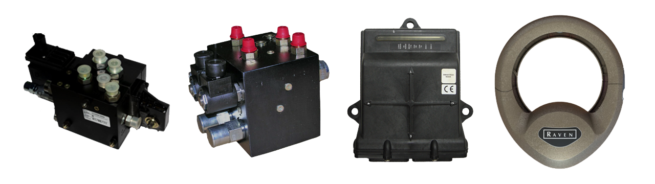
the steering controller The SmarTrax 3D node is the electronic control unit (ECU) for SmarTrax 3D steering. It takes the GNSS signal from the receiver, compensates it for changes in the terrain, and then passes the terrain-compensated signal to the field computer. From there, the guidance path is set in the field computer and then the SmarTrax 3D node controls the machine’s steering along that guidance path. There are inertial sensors built into the SmarTrax 3D node that measure the roll, pitch, and yaw of the machine. This will be an important factor in installation, calibration, and operation.
|
|
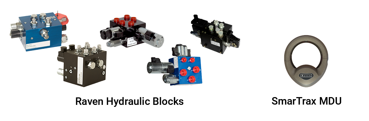
what drives the machine The steering mechanism can either be a hydraulic valve or a mechanical drive unit (MDU). The hydraulic valve directly controls the machine’s hydraulic steering system. The MDU installs onto the steering column under the steering wheel.
Some machines can be “steer ready.” SmarTrax 3D may work on a steer-ready machine if it has been validated to work and has a tune-set for the valve. For these machines, SmarTrax 3D will tie into the machine's existing hydraulic valve for control. |
|
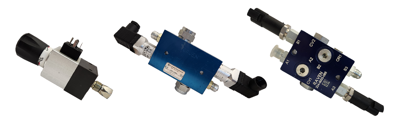
used on some SmarTrax Installations Some installations require the use of either a flow switch or pressure switch. These switches are hydraulic check valves used for detecting a change in flow or pressure in the machine's steering system when the steering wheel is manually turned. When the switch detects a change in flow or pressure, or a pressure differential in some cases, it will send a signal back to the SmarTrax 3D node telling it to disengage auto-steering.
These switches also allow for SmarTrax 3D to auto-steer when there is no change in flow or pressure. |
|
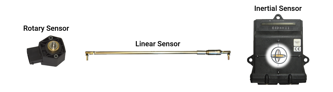
real-time feedback for wheel position or machine heading While there are inertial sensors built into the SmarTrax 3D node, it is still beneficial—and even required in some cases—to use physical sensors to measure what the wheels are doing. The two main physical sensors used are steering position sensors (SPS) and wheel angle sensors (WAS). These sensors are highly recommended for use in low-speed operations and front boom sprayers. The internal yaw reading from the SmarTrax 3D node will have difficulty operating in these situations.
|
|
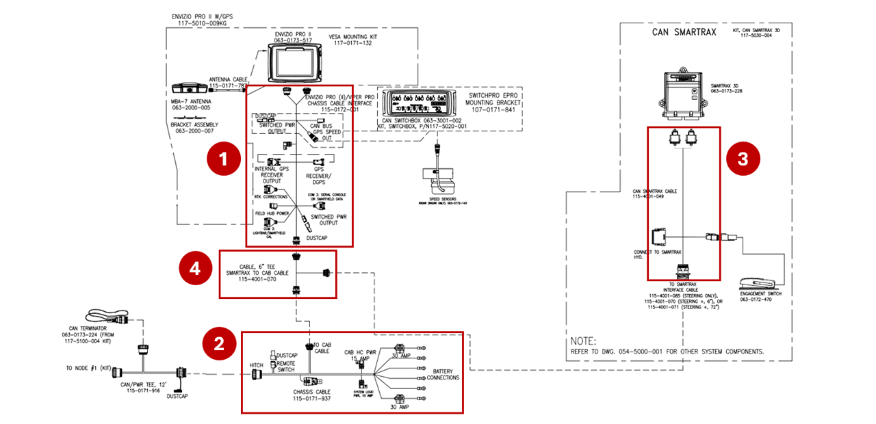
connecting it all together All communication between the CAN devices on the system happens over the system's cabling. With SmarTrax 3D, we use three to four specific cables. 1. Field computer or console cable
2. Chassis cable *
3. SmarTrax node cable
4. SmarTrax tee cable (when applicable)
* The chassis cable and SmarTrax tee cable are not used in a Generation 1 CANBUS system. Refer to the GNSS Signal Routing Examples section for some examples of the different generations of Raven CAN systems. |
|
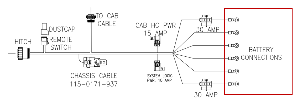
Gen 2 and newer cabling will use a chassis cable to provide power to the CANBUS components. Connect this cable directly to the battery and not to a power bar or other auxiliary power source. We want to make sure we are getting clean power to all devices for communication and control functionality.
|
|
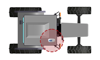
The antenna position on the roof is vital for operation. Give the antenna an unobstructed view of the sky. Do not place it next to anything that can get in the way of this view. Some antennas have a more "outward" view whereas other antennas have a more "up-and-out" view. You also want to avoid positioning the antenna close to any other devices, especially other receivers or transmitters, as they can interfere with GNSS signal reception.
If you are using magnet mounts for your antenna, it may be a good idea to clearly mark the mount location in case the antenna ever gets moved. That way you will know exactly where to place the antenna and have it match the offsets and measurements stored during setup and calibration. |
|
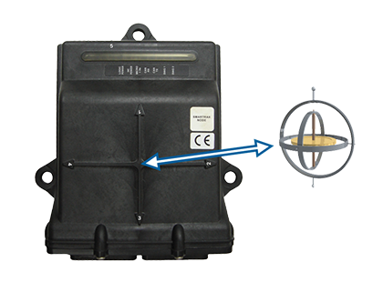
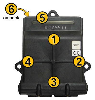
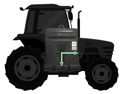
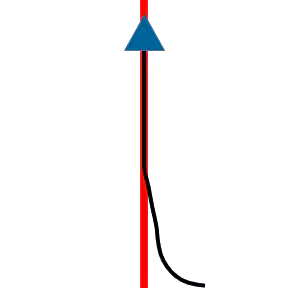
There are many things that are important to "get right" when installing and calibrating SmarTrax 3D, and mounting the node is no exception. The node must be installed so that one of the six numbers is pointing straight forward in the direction of travel and another arrow is pointing straight down to the ground. The front of the node will have four arrows numbered 1 through 4, and then number 5 will be the front of the node and 6 will be the back. Knowing these numbers is very important as they are required during setup.
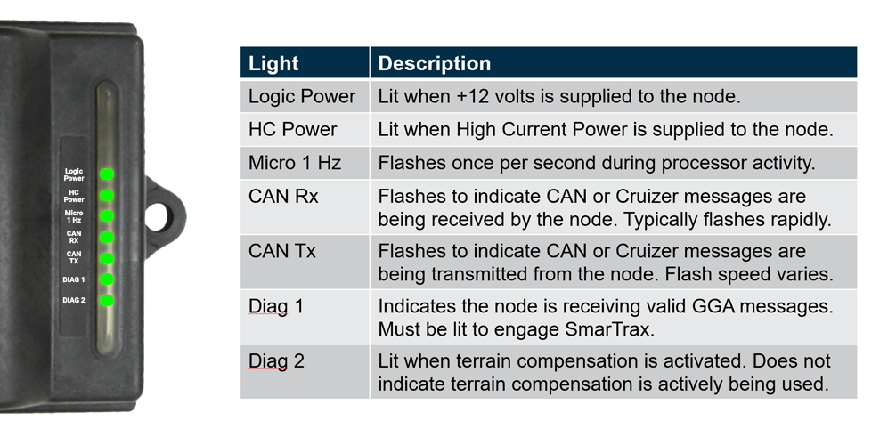
When securing the node, whether it is on the floor, behind the seat, or in a storage compartment, be sure to use all three mounting points. You will want to make sure there is no "wiggle" in the node because it can introduce error in the internal sensor readings and cause erratic steering performance. You also do not want to use rubber washers or any other type of shock absorber as this can also cause the node to "wiggle." It is also a good idea to mount the node someplace where you can see what the lights are doing. These lights are helpful in diagnostics and troubleshooting. |
|
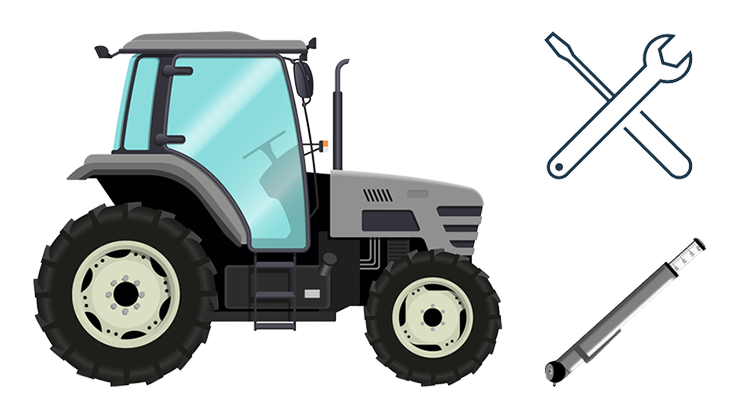
You will want the machine in good working condition before calibrating SmarTrax 3D. Check for and address any issues with the machine such as the hydraulic hoses and connections, steering linkages, the steering column if using SmarTrax MD, and tire pressure.
Remember, SmarTrax 3D can only perform within the capabilities of the machine, so it is best practice to make sure the machine is in the best possible operating condition. |
|
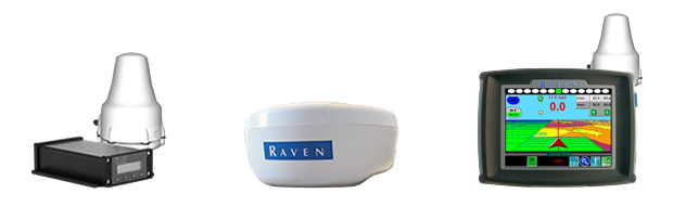
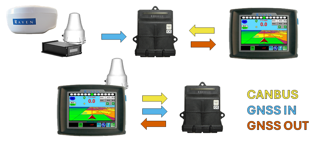
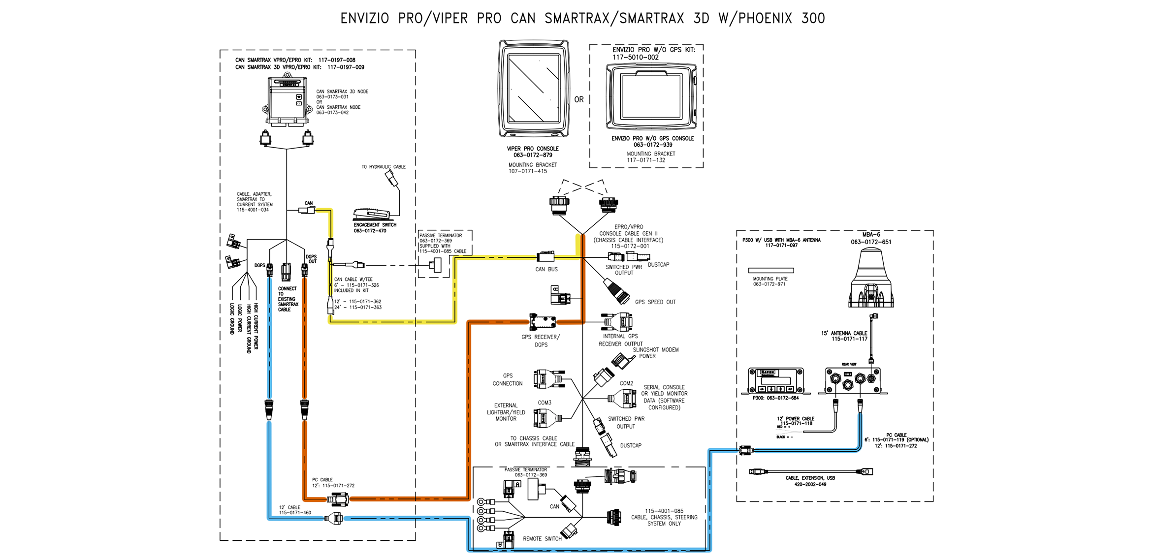
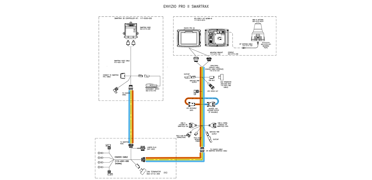
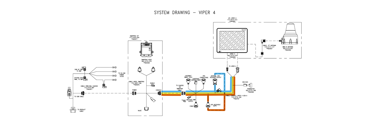
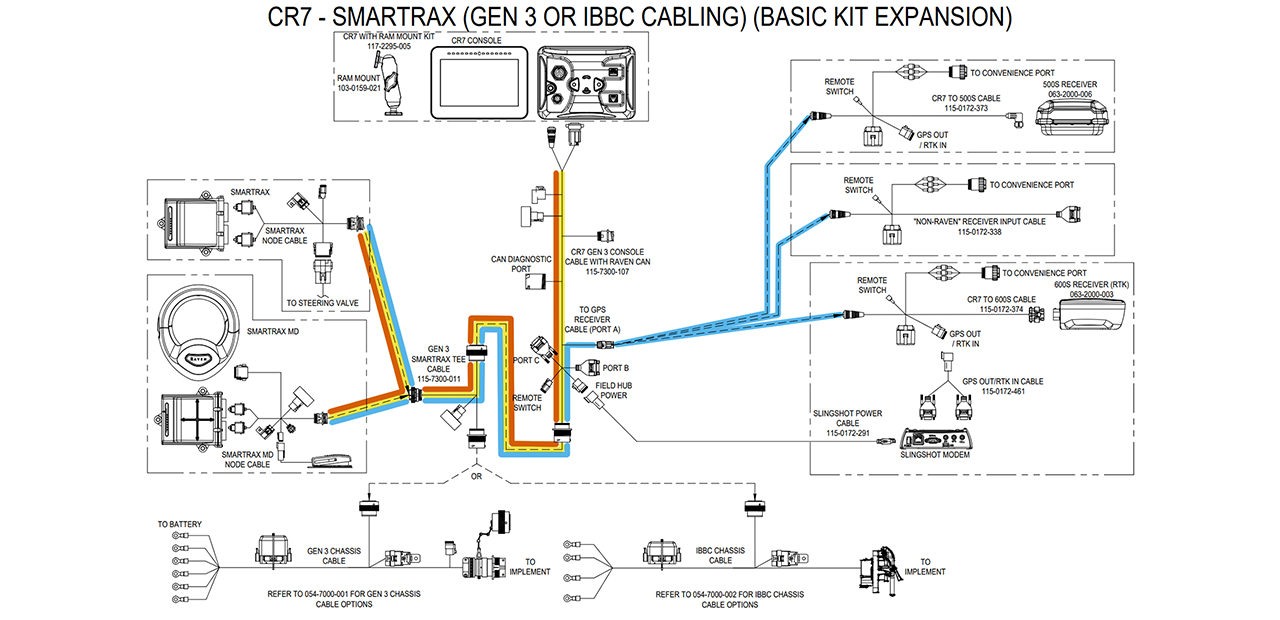
The components shown below represent the difference between external GNSS (top) and internal GNSS (bottom). Understanding the GNSS signal paths is important for installation and troubleshooting if something goes wrong.
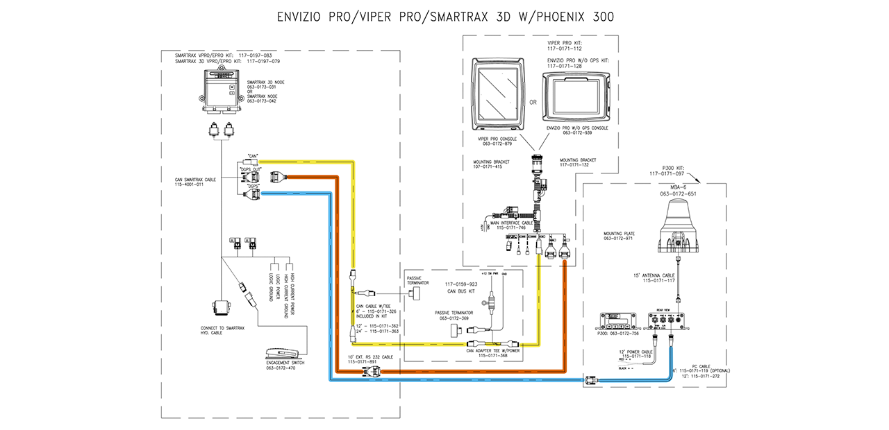
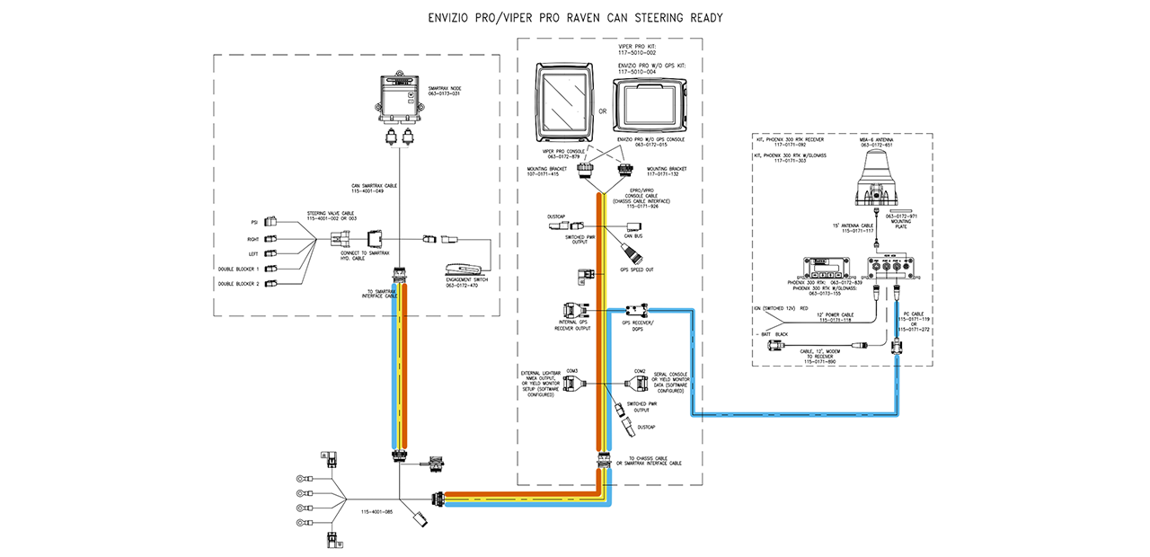
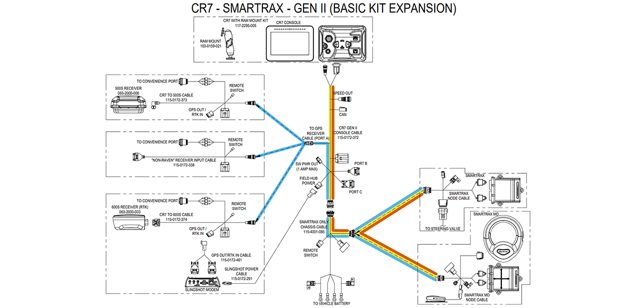
The drop-down sections below will have examples of the different generations of Raven cabling with internal and external GNSS receiver options. The colors shown in the arrows will help us visualize the signal path for the CAN communication between the field computer and SmarTrax 3D. Here, we are referring to the GNSS “IN” and “OUT” as they relate to the SmarTrax 3D node. This does not always apply to what is shown on connector labels, however, so keep this in mind. For example, the GNSS IN above is really a combination of the receiver’s output and the steering node’s input. Here it is easier to simplify these “IN” and “OUT” connections as they relate to SmarTrax 3D. |
|
Before you can proceed with calibration, you will need to configure the communication pathways for the GNSS receiver to SmarTrax, and then for SmarTrax to the field computer. We will only cover the generally required settings for the GNSS receiver to SmarTrax in this document. Refer to the calibration and operation manuals for specific information. The three NMEA messages SmarTrax needs are GGA, VTG, and ZDA. The table below has the required message rates along with a description for what the message provides.
You will also want to set the baud rates as follows:
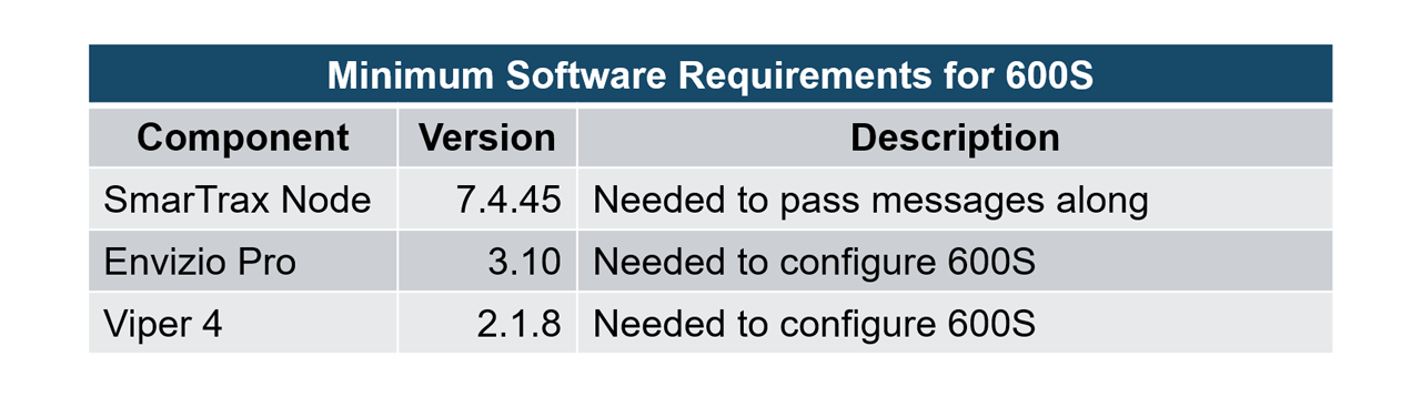
There are minimum software requirements for using a 600S receiver with SmarTrax 3D and either an Envizio Pro or Viper 4.
|
|
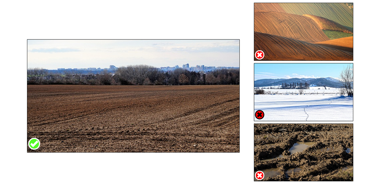
You will want to calibrate on flat, solid ground. Gradual slopes may not cause any issues during calibration, but you may need to be more thorough in your fine tuning later. Very soft soil, whether it is just very loose dirt, mud, or covered in snow, can introduce extra error in the steering calibration process. It causes wheel slippage, and it can also cause the machine to need to work harder to steer through it. Loose gravel and crushed rock can add error through jittery reactions in addition to slippage and extra effort like with loose soil or mud.
If you must calibrate on concrete or any sort of paved surface, you may need to dial down the minimum effort when you fine tune the system. These surfaces add more resistance to the tires, requiring extra effort when turning. You will want to take extra care in fine tuning if you calibrate on these surfaces. |
|
You will need to configure the following items with the calibration wizard:
Before you start calibrating, don't forget to turn on the road switch if one is installed. If using SmarTrax MD, the MDU has a road switch on the back of the device. |
|
The machine type is where you will pick the specific type of machine such as a rear boom self-propelled sprayer, front-steer tractor, or articulated tractor. The control device is the option for what is actually steering the machine.
|
|
The disengage calibration screen will be different depending on if you have a flow/pressure switch installed or if your valve has a pressure transducer. If using a flow/pressure switch, you may need to adjust the steering switch pressure on the hydraulic block. If you have a pressure transducer, you will have a disengage setting that can be adjusted directly in the calibration screen. For the engage switch calibration, start with the switch in the OFF position if using a rocker switch. SmarTrax will then look for a change in status for the type of switch you have installed (foot switch or rocker switch). |
|
Node orientation gets set during calibration and the forward and down arrows must keep pointing forward and down. This is why securely mounting the node, and without rubber washers, is so important. You tell SmarTrax which arrow is pointing forward, and it will automatically detect which arrow is pointing down.
|
|
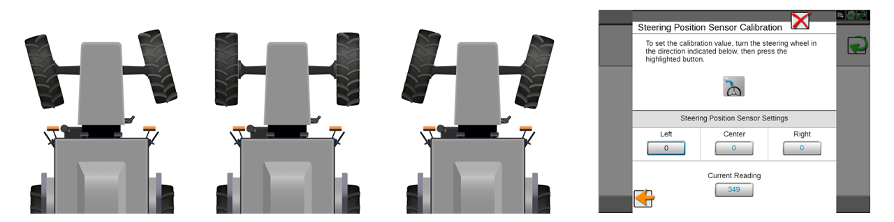
If an SPS or WAS is installed, you must calibrate it. The SmarTrax MDU will have a built-in sensor, and it will be part of the calibration process. Here you will calibrate the Left, Center, and Right positions for the sensor. We highly recommend for you to be moving while doing this part of the calibration. Driving slowly will be fine for this part, and it will make it easier to get accurate measurements for the sensor.
The range of the SPS/WAS values is limited to 10-1010 to prevent damage to certain types of sensors. Ensure the sensor is mounted securely to prevent damage during operation. The difference between the Left and Center values and Center and Right values must exceed 100. |
|
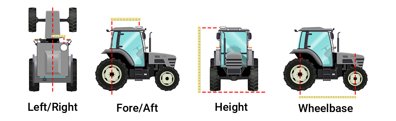
For this part of calibration, we need to know where the antenna is located on the machine. You will set the left/right, fore/aft, and height measurements for the antenna, and then you will enter the machine dimensions. The machine dimensions are used to position the fixed axle of the machine and the application point.
|
|
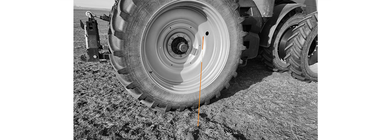
We recommend placing flags or markers outside of each rear wheel and aligned with the axle.
After you start the 3D calibration, drive forward and then make a turn in the shape of a light bulb. It doesn't matter which way you turn around as long as you only turn in one direction. Then bring the machine back to the wheel markers but facing the opposite direction. You can proceed once all numbers go back to the original text color in the display. |
|
Once you get to the part of the calibration process where SmarTrax will take control to learn what control efforts are needed for auto-steering, you will want to make sure the machine is ready. You will want to make sure the machine's hydraulics are at operating temperature, which it should already be warmed up after getting situated in the field and calibrating SPS/WAS values and 3D compensation. Set the engine RPM to a typical operating level. For self-propelled sprayers, have the booms racked. Even though you will be operating SmarTrax while applying product to the field, we want to avoid introducing any steering "whiplash" from the booms being extended. SmarTrax will make several gradual and sharp turns during steering calibration and having the booms extended will require SmarTrax to use more effort as the baseline. It is similar to needing good field conditions in that regard. For tractors, do not have any trailers or implements connected. We want to calibrate the baseline for just the machine here. You can fine tune for each implement condition later. If you are calibrating in a small area, or if the field has obstacles present, be prepared to disengage steering and try again. As a note, you will want to limit the number of stops and starts during calibration. If you need to stop and start multiple times, then you may need to find a more ideal place to calibrate. |
|
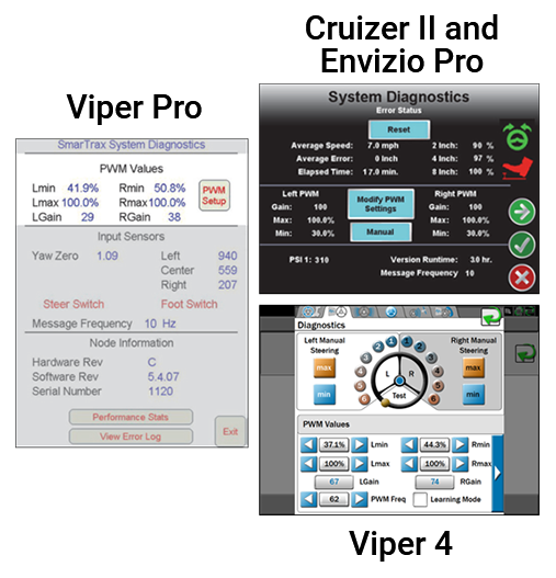
Before you start fine tuning SmarTrax settings, we recommend checking the values for the steering gains first. Look for a large difference between the gains for the left and right sides. It is not unusual to have a difference between the left and right, especially on older machines. However, a difference of 30% or greater may indicate a bad calibration or potential issue with the machine.
Steering gains are locked with SmarTrax 3D and are not user adjustable. |
|
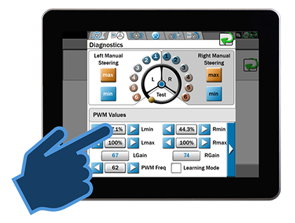
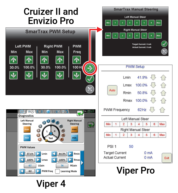
The next step in fine tuning SmarTrax is to make adjustments to the PWM values. You will want to do this before making any changes to the Sensitivity and Line Acquire settings because those settings work within the PWM values. The SmarTrax PWM values determine the voltage level or duty cycle (%) that is sent to the solenoid on the steering valve to engage the hydraulics. The Min and the Max are set based on the initial calibration. Mins will vary by machine, but they normally range between 20-45. Values around 20 are typically found in steer-ready machines and machines with very light/sensitive steering. Values of 40 and above are normally found in harder steering machines or machines with larger tires. The Max will typically be in the high 80 to 100 range.
You can use the "Min" button in the manual steering settings to test the minimum steering output. When making changes to the Mins, wait 30 seconds before you try steering again. This will make sure the setting has been fully accepted by SmarTrax. When steering a machine manually through the SmarTrax screens on a field computer, it is good to know that the Min button will apply at the Min PWM setting while the Max applies at the Max PWM setting. The other manual options are numbered 1 through 6. Each number will apply by the following approximate values: 1 is 20%; 2 is 30%; 3 is 40%; 4 is 60%; 5 is 80%; 6 is 100%. The Maxes usually do not need to be adjusted from what they are set to during calibration. You should only need to adjust the PWM values right after a calibration or at the beginning of a season. From there, you can adjust Sensitivity and Line Acquire as needed between different operators, fields, and more. |
Sensitivity is active when the machine is within 24 inches of the guidance line.
| A good Sensitivity setting should keep the machine on the line without needing to make any major corrections and very few minor corrections. |
| If too low, it will slowly weave along the line, slightly to the left and then slightly to the right while crossing the guidance line as it weaves. |
|
If too high, it will aggressively jerk back and forth along the line. The machine will mostly likely turn constantly as it tries to stay on the line. |
|
| Note: For SmarTrax software versions below 7.0, the Sensitivity setting is not compensated for changes in speed. | |
Line Acquire is active when the machine is farther than 24 inches from the guidance line.
| A good Line Acquire setting should approach the line smoothly without overshooting or steering too sharply. |
| If too low, it will be “lazy” in acquiring the line, which can often cause it to overshoot or drive past the line. If it overshoots, it can take longer to get back onto the line. |
|
If too high, it will try to get to the line quickly, often causing oversteering. It could possibly even “wobble,” meaning the machine may turn back and forth as it continues to move closer to the line. |
|
| Note: For SmarTrax software versions below 7.0, the Line Acquire setting is not compensated for changes in speed. | |
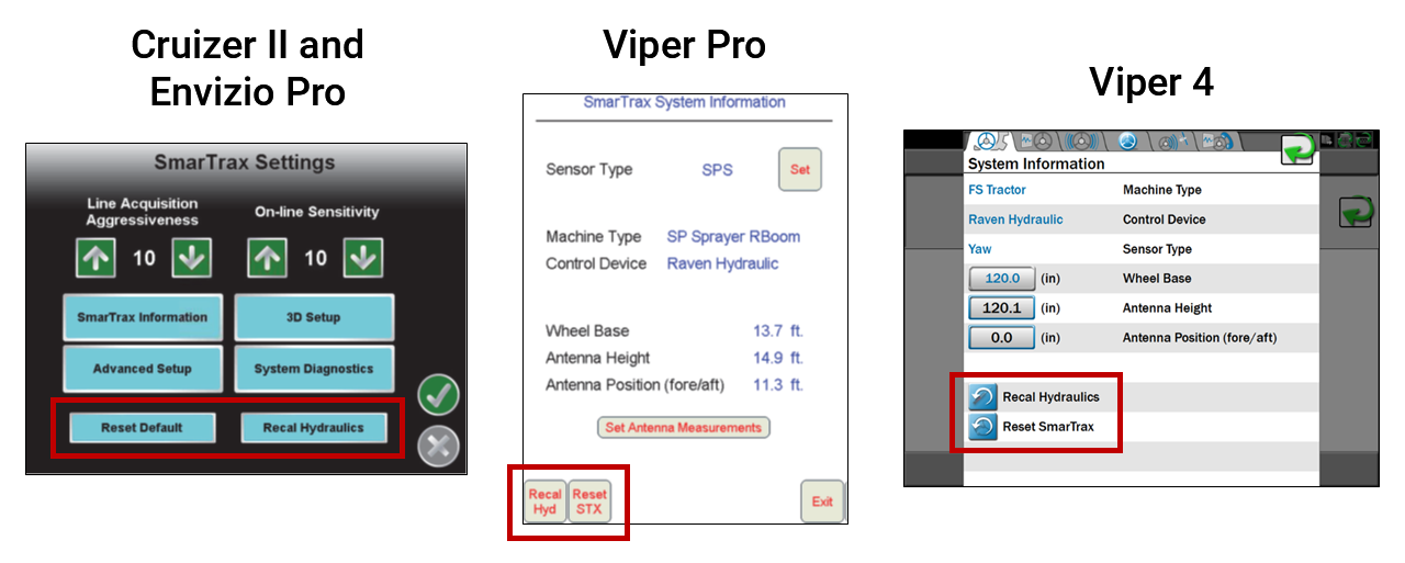
You can also recalibrate terrain compensation at any point.
Recalibrate Hydraulics...
|
|
Below is the basic troubleshooting checklist we would use if we were troubleshooting a system. There is more information on troubleshooting in the SmarTrax calibration and operation manual. The troubleshooting section will have information on error messages and operation issues along with possible causes and how to correct the problem. Machine
Settings
Installation
Measurements
GNSS Informaton
Node
Valve
|
|
The Diag 1 light cannot be used to verify if the field computer is receiving the GNSS signal. This light only indicates if the SmarTrax node is receiving the signal from the GNSS receiver. If the node is getting the signal but the field computer is not, check settings and cabling between the node and field computer. The HC Power light is not used with steer-ready installations or with SmarTrax MD. |
|
In general, it is recommended to be at the latest software version for all legacy devices in a Raven SmarTrax steering system. Exceptions include:
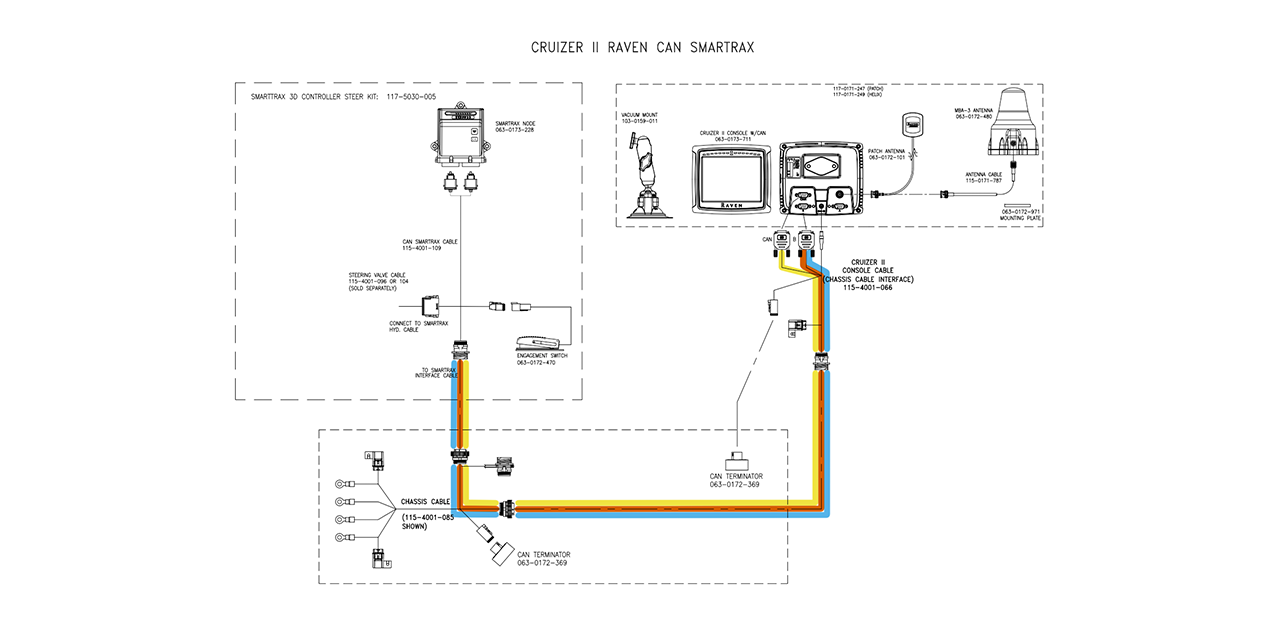
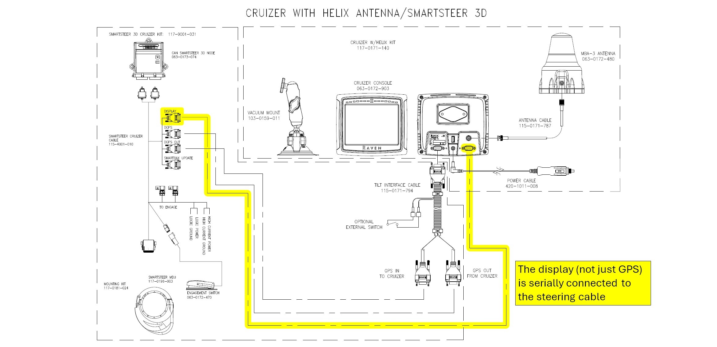
SmartSteer is supported in SmarTrax versions 6.0.41 and below and version 6.0.82. This system drawing is an example of a Cruizer being serially connected to a SmartSteer node. The 115-4001-010 cable also works with the SmarTrax node, so this also can be an example of using the SmarTrax node with a SmartSteer MDU.
The main thing to remember with this drawing is that the connection between the steering cable and the display is using serial. Notice how this is labeled as “Display” on the steering cable. This is different than the “GPS IN” and “GPS OUT” connections being serial for GNSS communication which is typical for SmarTrax systems. In more recent SmarTrax systems with Cruizer II, Envizio Pro, Viper Pro, and Viper 4, the display connection uses CAN. You can go back to the Cruizer II Gen 2 cabling section to see it is using CAN communication even though the connector going into the Cruizer II is a serial connector. This Cruizer system is using serial communication throughout. |